Search This Blog

27 July 2022

Over current and earth fault protection

Over current protection and earth fault is simple protection. Being low cost protection it is widely used across all levels. For lower voltage levels it is main protection, and for higher voltage levels it is used as backup protection. The reason being this protection does not have clear boundaries of protection.

Over current protection is for phase current and earth fault is for neutral current (residual current). The characteristics for both protections are same.


This protection is of two types: definite time (DT) or inverse definite minimum time (IDMT).

Definite Time (DT): In this type, protection will start when current reaches a set value, and protection will operate after a set time. For example, we for a transformer having maximum through fault current of 100A we can set DT protection 110A with time delay 100ms. In this way protection will operate in case of faults inside transformer only. For faults on downstream current will be less than 100A and protection will not operate.

Inverse Definite Minimum Time (IDMT): In this type, protection will start when current reaches a set value, and operating time of protection will depend on the level of current. If current is very high compared to set value, protection will operate fast. If current is slightly high from set value, relay will take more time to operate. In this way, a curve can be drawn between current and time for each relay. There are standard curves for which relays are designed. User can select from these curves as per requirement. For mechanical relays these curves are fixed as per design. However, in case of static / numerical relay curve can be selected form settings of relay.


For example, we have set relay in IDMT standard inverse for a transformer. Full load current of the transformer is 100A, and we have set IDMT start at 120A. The relay will start when current increases beyond 120A. If the current is 1200A, which means 10 times of set value. For 10 times current, the operating time is 2s (from curve). There is another setting called Time multiplier setting (TMS), say it is set at 0.4 for this transformer. The operating time of relay will be 0.8s.

If fault current is 240A, which means double of set value. For double current the operating time is 10s. The operating time of relay will be 4s.

In this way, relay will operate in 800ms for fault current of 1200A and in 4 sec for fault current of 240A

The operating time can be calculated as per below (IEC):

Standard inverse: t = TMS x 0.14 / [(Ir^0.02) – 1]

Very inverse: t = TMS x 13.5 / [Ir – 1]

Extremely inverse: t = TMS x 80 / [(Ir^2) – 1]


13 March 2022

Time synchronization

Introduction: After any disturbance in power system, analysis for cause of disturbance requires sequential events from relevant protection and control devices. Therefore, all numerical IEDs (relays and controllers) needs to be time synchronized for proper sequence of events in chronological order. 

Generally IEDs are time synchronized by one of the following method:
  1. Pulse Per Minute (PPM)
  2. Inter-range instrumentation group timecode-B (IRIG-B)
  3. Simple Network Time Protocol (SNTP)
  4. Precision Time Protocol (PTP)
PPM: Time of the relay has to be set once manually, only seconds and milliseconds will be reset to 00.000 after receiving pulse from time synchronization equipment. It is simplest way of time synchronization. Large number of relays can be synchronized by connecting in parallel. Its accuracy depends on accuracy of internal clock as after synchronization it has to run on internal clock for one minute untill next pulse is received. Being obsolete system it is rarely used these days.

IRIG-B: It is standard format for transferring time information. Information can contains data for day of year, Hours, Minutes, Seconds and milliseconds.Data is transmitted by moduling on 1KHz sine wave through co-axial cable. Accuracy of microsecond level can be achieved. 

SNTP: It is time synchronization using Local Area Network (LAN) system. GPS equipment works as server and sends time information, which contains complete data Year, Month, day, Hours, Minutes, Seconds and milliseconds. All the IEDs get time information from server and time is synchronized. Its accuracy is low as delay in network components is not compensated. Accuracy of millisecond level can be achieved.

PTP: It is used where more accuracy is required than provided by SNTP. In PTP delay in network components is calculated by system and compensated by modifying time stamps. In this way, accuracy of nanosecond level can be achieved.

Controlled switching

Introduction: In AC system, magnitude of current and voltage signal are always varying in time domain. Whenever opening command is given to a circuit breaker (CB), there may be some current flowing depending on the instant of contact separation. Magnitude of this current will be different for three phases, as they will be passing through different position (angle) at any point.

CB will quench the arc at next current zero. The duration of arc will depend on position of current wave at the moment of separation. As we know, longer the duration of arc, larger the heat generated and larger the contact deterioration. Therefore, best time of opening instant will be just before the current zero to reduce arcing time. Opening at exact current zero will not work due to the reason that the speed of contacts will be slow and recovery voltage across contacts will be larger than dielectric strength gained. This will result in to restrike across contacts and arc will be quenched at next current zero (another 10ms for 50Hz system). Further there may be open time variation due to mechanical reasons in CB for each operation.

Controlled Switching Device (CSD): EHV class CBs, which are electrically ganged, have different operating mechanism for each CB pole. CSD device is used to operate all three CB poles at different times so that arcing in each phase is minimum. 


For proper operation of CSD, CB mechanical opening time for each phase is to be measured and entered in to CSD relay. As shown in image below, delay of 3.3ms (for 50Hz system) is to be provided for achieving opening of all phase just before current zero.


CSD is used only for manual operation due to added delay in opening. Protection trip will be issued to CB directly without and controlled switching.

CSD is used mainly in following applications:
  1. Reactor opening: to avoid current chopping
  2. Transformer charging: to avoid high inrush current
  3. Capacitor charging: to avoid high inrush current
  4. Transmission line charging: to avoid switching voltage surges

Floating DC system and DC earth fault relay

Introduction: DC supply is widely used as auxilliary supply for control and protection system. For larger systems 110V or 220V DC supply is used. For reliability both positive and negative terminals of DC supply are isolated from ground. This is system is called floating DC system.  

Floating DC system has advantage that single earth fault will not cause any outage. Second earth fault may blow the fuse or maloperation of protection. 

DC earth fault relay: For identification of earth faults in early stages, sensative DC earth fault relay is used. 

DC earth fault relay is connected to midpoint of two high value resistors (~ 20kΩ). In normal condition as there will be no path for current to earth, there will be no current in relay element. During a DC earth fault in +ve or -ve terminal, current will flow in to earth by completing return path through DC earth fault relay element. Typical setting for DC earth fault relay is ~ 5mA.

This will cause operation of DC earth fault relay and give alarm to operator. Earth fault can be identified and rectified by maintenance staff before second earth fault. As high value resistance is used in earth fault circuit, fault current will be very low and identification of exact feeder and loaction of fault is difficult. Following methods are generally used for identification of location:
  1. Switching off feeders one by one.
  2. Using DC earth fault locator instrument, which inject low voltage low frequency signal of ~5Hz in DC system. Faulty feeder is identified by measuring leakage current using tuned clamp on meters.

06 March 2022

Interlocking schemes

Introduction: In power system following switchgears are used for operation purpose:

  1. Circuit Breaker (CB): It has capability to close or open electric circuits under load or fault conditions. 
  2. Disconnector (or Isolator): It can close or open electric circuits under no load condition.
  3. Earth switch: It is used to earth primary conductors for maintenance purposes.

Above description leads to following requirements:

  1. CB can be opened or closed on no load or full load or fault condition. Therefore, no check is required for disconnector or earth switch status. However, for safety and security of grid, synchronization check is carried out in grids.
  2. Disconnector should be operated only when load current is not flowing, i.e. CB should be open. Further, if earth switch is closed, closing of disconnector may cause fault. Therefore, before closing disconnector, associated earth switch status needs to be checked.
  3. Earth switch should be operated only when primary conductor is already de-energized. Therefore, status of associated disconnectors needs to be checked. In case of long transmission lines, that may be charged from remote end, status of remote end switchgear may not be available. In this case presence of voltage can be checked for interlocking.

For example, let's take a simple single bus bar scheme:


  • 189A can be operated when: 152 is open, Bus earth switch is open
  • 189B can be operated when: 152 is open
  • 289A can be operated when: 252 is open, Bus earth switch is open
  • 289B can be operated when: 252 is open
  • Bus earth switch can be operated when: 189A is open, 289A is open

For one and half breaker scheme:


Disconnector 389A can be operated when:
  • CB 352 is open
  • Earth switch 389AE and 389BE is open
  • Bus-2 Earth switch is open
Disconnector 389B can be operated when:
  • CB 352 is open
  • Earth switch 389AE and 389BE is open
Disconnector 389L can be operated when:
  • CB 352 & CB 252 is open
  • Earth switch 389LE is open
ES 389AE can be operated when:
  • Disconnector 389A & 389B is open
ES 389BE can be operated when:
  • Disconnector 389A & 389B is open
ES 389LE can be operated when:
  • Disconnector 389L should be open
  • There should be no voltage in line

23 January 2022

VT supervision

Introduction: For protection relays, analogue inputs are connected from Current Transformers (CT) and Voltage Transformers (VT). VT is a voltage source, any short circuit in wiring will cause heavy current to flow in VT winding. This may result in failure of VT. Therefore, Connection from VT is always with fuse or MCB to take care of short circuit / overload.

Now it is evident that in case of fuse failure, relay will not get any voltage from VT. Some of the protections may see this as abnormal condition in system and may cause unwanted trip or may not trip in actual fault. For example:

  1. Distance relays measure Impedance from Voltage and current (Z = V/I). If there is no voltage (V=0), Z will also be Zero. This will cause trip of distance protection.
  2. Directional Overcurrent relay derives direction by comparing angle of voltage with current. If there is no voltage, it can not measure its angle. Therefore, it will not operate in case of actual fault.
Absence of voltage or lower voltage to relay may be due to one of the following reason:

  1. Actual fault on primary side of power system, which has caused voltage to dip. One disturbance record for this condition with B-N fault is given below. We can see presence of VN (3V0) with significant IN (3I0).

  2. No actual fault on primary side, only secondary fuse fail. One disturbance record for this condition with C-phase fuse failure is given below. We can see presence of VN (3V0) without any significant IN (3I0).

It is important for protection relays to differentiate between above two conditions and declare VT fuse fail only when there is no fault in primary side. VT fuse fail condition leads to blocking of certain protection functions and generation of alarm to operator.

Method of detection: VT fuse fail may be classified in two types:

  1. Single phase VT fuse fail, when fuse is used in VT secondary circuit and it has blown due to short circuit.
  2. Three phase VT fuse fail, when MCB is used in VT secondary circuit and it has tripped. There may be another case when VT selection is used and VT selection relay has failed to operate.  

Single phase VT fuse fail: Its detection is easy and reliable. In case of actual single phase fault, voltage will decrease and current will increase for that phase, ie. there will be zero sequence current and zero sequence voltage present in system. 

However, in case of VT fuse fail, currents will remain same and only voltage will be decreased. Most of the relays detect it by presence of Zero sequence voltage without presence of Zero sequence current in system. In some case Negative sequence voltage and Negative sequence current is used for detection.

Three phase VT fuse fail: It is a little unreliable and works to some extent. Due to absence of all three phases there will not be any zero sequence or negative sequence voltage in the system. 

It can be detected by change in voltages without any change in currents by comparing with previous cycles values (ΔV and ΔI). But in case three phase fuse fail condition is persisting, and current goes below a certail level, due to load variation. Relay may detect it as dead line condition (no voltage and no current). This will reset three phase VT fuse fail condition. Now sudden rise of current can cause trip of relay. Therefore, three phase fuse fail is a little unreliable. 

Or, relay can detect MCB trip through auxilliary contact of MCB, if MCB is used in secondary circuit.


16 January 2022

Add-on stabalization technique in Bus Bar protection

 Introduction: In earlier post we have discussed about Bus bar differential protection.

For Low impdance bus bar protections, different manuafacturer use different algorithm to avoid mal-operation of relay during CT saturation.

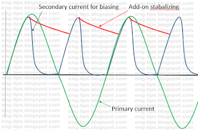
Add-on stabalization technique: One of the method is use of Add-on stabalization technique for detecting internal / external faults. Add-on stabalization function adds additional current to biasing current.


Phase comparison technique in Bus Bar protection

Introduction: In earlier post we have discussed about Bus bar differential protection.

For Low impdance bus bar protections, different manuafacturer use different algorithm to avoid mal-operation of relay during CT saturation

Phase comparison technique: One of the method is use of Phase comparison technique for detecting internal / external faults. Phase comparison function compares the phase-angles of the fundamental components of all the feeder currents.

During a through-fault, at least one of the currents is ~180° out of phase with the others. In case of CT saturation its magnitude may be lower but relay can compare its angle to distinguish internal fault from external fault. 

During internal fault of bus bar, currents from all feeders will flow towars busbar. This means, phase angle of all currents will be nearly same.

If the phase-angles of all the feeder currents of a protection zone lie within a band of ~74° (typical value), the phase comparison function decides that there is an internal fault.

For proper operation, it is necessary to exclude feeders conducting very little or no current from the comparison to prevent noise generated by them.

A minimum current is therefore determined below which a feeder is excluded from the phase comparison. Typical settings are 0.8 IN for the phase currents and 0.25 IN for the neutral current.

Tripping only takes place if the differential current and the stability factor (Slope) are both above their pick-up settings and the phase difference between the currents is less than setting.


Bus bar differential protection

Introduction: Bus bar is important element in a power system due to following reasons:

  1. Fault current is higher for bus bar faults, as every feeder will contribute in fault current and bus bar impedance is very low.
  2. Bus bar fault may lead to outage of many feeders, depending on bus bar scheme. Mal-operation in case of out of zone fault will also cause un-necessary outage. Therefore, generally trip decision is taken after confirmation by two different components in bus bar protection.
  3. Non-operation of busbar protection in case of actual fault is very dangerous for equipment, persons working in system and power system itself. It will lead to delayed fault clearance and impact larger area. To avoid this redundant bus bar protection schemes are used for important installations.
  4. Bus bar has to compare currents of all feeders connected to it, there is requirement of all CTs having similar characteristics to avoid mal-operations in case of through faults.
  5. Being smaller sections, faults are considered rare for bus bars. As bus bar protection cost is higher, generally bus bar protection is not used for smaller systems.
Principle of operation: Differential protection works on the principle of Kirchhoff's current law, which states - "The current flowing into a node (or a junction) must be equal to the current flowing out of it" or equivalently "The vector sum of currents in a network of conductors meeting at a point is zero."

Bus bar can be considered as node, where all feeders are connected. The vector sum of all these currents shall be zero. 

For understanding we may consider one bus bar with two feeders.


Case-1: For out of zone fault, current through relay will be I1 - I2, which is zero. 


Case-2: For in zone fault, current through relay will be I1 + I2, which will have higher value depending on source behind Feeder-1 & Feeder-2.

The protection shown in this example will have following issues:
  1. It may trip for out of zone faults due to CT. Ratio error during heavy current
  2. Unstable due to saturation of CT magnetic circuit during heavy current
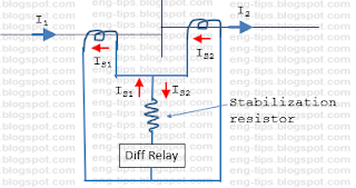
For avoiding this we have to increase stability of bus bar protection for these conditions. One solution would be to add one stabalization resistor in series of differential relay. It is similar to Transformer REF relay 


In this case impedance of bus bar protection is high due to series resistor, therefore protection is called high impedance differential protection. As all CTs are to be connected directly in parallel, all the CTs should have same CT ratio.

Second solution is to measure through fault current for each feeder and use this current for biasing element. It is similar to Transformer differential protection.


In this case impedance of bus bar protection is low, therefore protection is called low impedance differential protection. As every CT is connected directly to differential relay, relay has values of every individual feeder current. Relay calculates Differential and Biasing currents based on internal algorithm and settings adopted. 

IDifferential  = |I1 + I2 + ……. In|

IBias = |I1| + |I2| + ……. |In|

Stability factor k = IDifferential / IBias


There is a minimum value of Differential current, below which relay will never operate. Above this differential current, operation is decided by ratio of Differential current to Biasing current. For bus bar protection fault current levels are high, and CT saturation is expected to cause error in CT secondary currents. Different manufacturers use different techniques to take care CT saturation, some are discussed below:
Bus bar protection becomes more complicated when CT switching is possible, line in Double busbar scheme. 
Now, relay has to check which feeders are connected to bus bar through status of disconnectors. There may be discripancy in status due to problem of an auxilliary switch or when performing bus shifting in charged condition. Bus bar relay may see differential current due to time mismatch between actual position of disconnector and auxilliary switch of disconnector.

Additional Check zone is used in this case. Check zone calculates vector sum of all feeders in and out of a station, considering all bus bars as one bus bar, whithout any CT switching.
For double bus bar, Tripping is issued as below:
  • Bus Bar-1 : BB Zone-1 operated and Check Zone operated
  • Bus Bar-2 : BB Zone-2 operated and Check Zone operated