Search This Blog

16 January 2022

Bus bar differential protection

Introduction: Bus bar is important element in a power system due to following reasons:

  1. Fault current is higher for bus bar faults, as every feeder will contribute in fault current and bus bar impedance is very low.
  2. Bus bar fault may lead to outage of many feeders, depending on bus bar scheme. Mal-operation in case of out of zone fault will also cause un-necessary outage. Therefore, generally trip decision is taken after confirmation by two different components in bus bar protection.
  3. Non-operation of busbar protection in case of actual fault is very dangerous for equipment, persons working in system and power system itself. It will lead to delayed fault clearance and impact larger area. To avoid this redundant bus bar protection schemes are used for important installations.
  4. Bus bar has to compare currents of all feeders connected to it, there is requirement of all CTs having similar characteristics to avoid mal-operations in case of through faults.
  5. Being smaller sections, faults are considered rare for bus bars. As bus bar protection cost is higher, generally bus bar protection is not used for smaller systems.
Principle of operation: Differential protection works on the principle of Kirchhoff's current law, which states - "The current flowing into a node (or a junction) must be equal to the current flowing out of it" or equivalently "The vector sum of currents in a network of conductors meeting at a point is zero."

Bus bar can be considered as node, where all feeders are connected. The vector sum of all these currents shall be zero. 

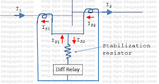
For understanding we may consider one bus bar with two feeders.


Case-1: For out of zone fault, current through relay will be I1 - I2, which is zero. 


Case-2: For in zone fault, current through relay will be I1 + I2, which will have higher value depending on source behind Feeder-1 & Feeder-2.

The protection shown in this example will have following issues:
  1. It may trip for out of zone faults due to CT. Ratio error during heavy current
  2. Unstable due to saturation of CT magnetic circuit during heavy current
For avoiding this we have to increase stability of bus bar protection for these conditions. One solution would be to add one stabalization resistor in series of differential relay. It is similar to Transformer REF relay 


In this case impedance of bus bar protection is high due to series resistor, therefore protection is called high impedance differential protection. As all CTs are to be connected directly in parallel, all the CTs should have same CT ratio.

Second solution is to measure through fault current for each feeder and use this current for biasing element. It is similar to Transformer differential protection.


In this case impedance of bus bar protection is low, therefore protection is called low impedance differential protection. As every CT is connected directly to differential relay, relay has values of every individual feeder current. Relay calculates Differential and Biasing currents based on internal algorithm and settings adopted. 

IDifferential  = |I1 + I2 + ……. In|

IBias = |I1| + |I2| + ……. |In|

Stability factor k = IDifferential / IBias


There is a minimum value of Differential current, below which relay will never operate. Above this differential current, operation is decided by ratio of Differential current to Biasing current. For bus bar protection fault current levels are high, and CT saturation is expected to cause error in CT secondary currents. Different manufacturers use different techniques to take care CT saturation, some are discussed below:
Bus bar protection becomes more complicated when CT switching is possible, line in Double busbar scheme. 
Now, relay has to check which feeders are connected to bus bar through status of disconnectors. There may be discripancy in status due to problem of an auxilliary switch or when performing bus shifting in charged condition. Bus bar relay may see differential current due to time mismatch between actual position of disconnector and auxilliary switch of disconnector.

Additional Check zone is used in this case. Check zone calculates vector sum of all feeders in and out of a station, considering all bus bars as one bus bar, whithout any CT switching.
For double bus bar, Tripping is issued as below:
  • Bus Bar-1 : BB Zone-1 operated and Check Zone operated
  • Bus Bar-2 : BB Zone-2 operated and Check Zone operated

22 October 2021

Instrument Security Factor (ISF) of Current Transformer

Instrument security Factor (ISF) is used for specifying current limit, by which current will be delivered by a current transfprmer (CT) during fault conditions. 

ISF is used for metering class CTs. For protection class CTs, there is similar term called Accuracy Limit Factor (ALF).

Metering instruments like energy meters, transducers etc. are meant for measuring electrical quantities with high accuracy under normal operation. Measurement under fault condition is not required and insignificant due to short duration of faults. Metering instruments are designed to carry current upto a certain level. 

For example, an energy meter used with CT of 1000/1A ratio carries maximum 1A under full load. Therefore its input current carrying paths needs to be designed for current upto 150 to 200% of rated current (say 2A continuous) . For fault conditions, which will prevail for short duration, it should withstand upto 5A or 10A. But in case of severe fault of 40kA or 50kA on primary side, secondary current may go upto 40A or 50A. If meter is to be designed for such heavy currents its size and connections will be bulky. Its cost will go up and accuracy will go down. Therefore, CT core is designed to saturate at such heavy currents and maximum secondary current is specified as ISF.

ISF is ratio of rated instrument limit primary current to rated primary current. If ISF is specified as 5 for a 1000/1A CT, then CT metering core will saturate at 5000A primary and current in secondary will not go above 5A. Sometimes, auxiliary reactors are used to achieve ISF limit.

Equivalent circuit of CT:

IP = Primary current

IS = Secondary current

VS = Secondary voltage

ZE = Exciting impedance

IE = Exciting current

RS = Secondary resistance

XL = Leakage reactance

ZB = Burden impedance 

Effect of burden on ISF: ISF is specified for a certain burden. If actual burden is different from rated burden, ISF will change as below:

ISF at actual burden = ISF at rated burden x (Rated burden / Actual burden)

* Internal secondary winding resistance of CT to be added for calculating burden.

For example, for a CT with rated burden 20VA and ISF 5, if actual burden is 10VA, ISF will be =5 x (20/10) =10. I.e. maximum secondary current will be 10A.