The Disturbace Record (DR) files are used to analyse faults in power systems. DR continuosly record Analogue Signals (voltages, currents etc,) and Digital signals (Status of CB, protection operation etc.). As the memory of disturbance recorders is limited, the recorded data is flushed out continuosly on First-in-First-Out basis, so that the data for last few seconds (typically 1-5 sec) is always in the memory of DR. When they any fault occurs the Disturbance Recorder receives command to save the data in its memory. DR will record pre-fault and post-fault data as per settings already done in DR. Typical values for feeder DR may be Total fault duration = 2.0 sec, Pre-fault time = 0.5 sec, Post-fault time = 1.5 sec.
The disturbance record can be extracted sebsequently from PC for further analysing. The standard file format for saving this data is COMTRADE file format which has following files with same name and different extensions:
- Configuration file: *.cfg extension
- Data file: *.dat extension
- Header file: *.hdr extension
- Information file: *.inf extension
Sample screenshot of DR file in WAVEWIN (one of the DR evaluation software) :-
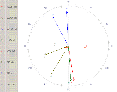
The same data can also be viewed in vector form :-
Normal condition
Faulty condition (A - phase to Ground fault)
CFG file can be opened in any DR evaluation software like WAVEWIN, SIGRA etc. All the screenshots here are given for Wavewin software as it is provided alongwith ABB and GE make relay softwares.
In the above image A-phase voltage has been taken as reference signal. Any analogue signal can be set as reference by single clicking on it. After single clicking it is selected and shown in red colour.
Wavewin has many advance features like
- Fault location calculation: Click here for detailed procedure
- Creating software analogue channels from one or more available analogue channels by putting some calculations like vector sum / difference of some channels. Mutiply / divide any channel by some constant etc.
- Merging two or more DR files manually or automatically by time stamps.


